Author Topic: How does this circuit provide
constant current?
jeff1500
Flashaholic
Member # 529
posted 12-19-2002 06:49 PM
--------------------------------------------------------------------------------
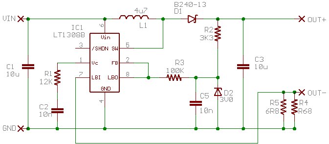
Here's a link to a very well made LS flashlight conversion using a
Linear Technology LT1308B:
http://nedkonz.dhs.org:8080/Ned/27
Looks like it has some extra circuitry that changes a step up voltage regulator into a constant current provider.
He says:
quote:
--------------------------------------------------------------------------------
The secret here is to use the low-battery comparator (LBI and
LBO pins) to sense the current. When the voltage across R5 is lower than
200mV, the LBO pin is pulled low, causing the output voltage to increase.
So the output is a sawtooth of a few mA around the current setpoint.
--------------------------------------------------------------------------------
How does this work?
--------------------
My CPF circuit collection is at this address:
https://edusite10.tripod.com/led3/index.html
--------------------------------------------------------------------------------
Posts: 352 | Registered: Jul 2001 | IP: Logged |
Jonathan
Flashaholic
Member # 1022
posted 12-19-2002 07:32 PM
--------------------------------------------------------------------------------
Ned Konz is a member here...
http://www.candlepowerforums.com/cgi-bin/ultimatebb.cgi?ubb=get_topic&f=3&t=001584
Most chips have a single comparitor, used to detect and adjust the output voltage. These chips have two comparitors; the LBI/LBO pins are normally used to shut down the chip when the input battery voltage falls below a minimum.
What Ned does is use this comparitor to regulate the output, by running the output current throug a low value sense resistor. The circuit turns on and off to maintain about 200mV across this sense resistor.
-Jon
--------------------------------------------------------------------------------
Posts: 345 | From: Boston, MA | Registered: Dec 2001 |
IP: Logged |
MrAl
Flashaholic
Member # 689
posted 12-20-2002 03:00 PM
--------------------------------------------------------------------------------
Hello there,
To add to what Jonathan was saying:
When the sense voltage rises above 200mv the
chip shuts the output off, and this means the
output current starts to ramp down to a lower
level. Since the 200mv depends on the current
THROUGH the led, when the output current gets
too high it shuts the output off, so the current
starts to ramp down to a lower level.
When the current gets down to a low enough level,
the sense voltage falls to a value lower
then 200mv and the chip senses this and allows
the output to start pulsing again which causes
the output current to again rise. This cycle
repeats over and over and usually at a frequency
lower then the normal oscillation frequency of
the chip. This also causes sub harmonics to
appear at the output across the LED.
Good luck with your LED circuits,
Al
--------------------
LED's vs Bulb's, the battle is on.
--------------------------------------------------------------------------------
Posts: 578 | From: New Jersey | Registered: Sep 2001 |
IP: Logged |
jeff1500
Flashaholic
Member # 529
posted 12-20-2002 04:56 PM
--------------------------------------------------------------------------------
I think I'm starting to understand. Do you agree with the following:
?
Vout = 1.22(1 + (R1/R2))
These are the R1 and R2 values from the datasheet schematic not the constant current schematic.
The output voltage goes up when R1 gets large and R2, which connects
to ground, gets small. So connecting FB to ground makes the output voltage
spike up.
------------------------
Then on the constant current circuit:
The sense resistor is in series with the output led so it's plus side voltage, Vsense, increases with output current.
At startup, Vsense, which equals V-LBI, is low, so that makes LBO ground, which makes FB ground, which makes Vout jump up.
High Vout charges C5 through R2. D1 prevents backflow from C3 when it discharges.
Then higher Vout increases current through the output led, raising Vsense = V-LBI, so LBO goes to open circuit (high impedence).
V-FB is then whatever FB sees at the plus side of C5 through R3. This makes Vout drop to a low value.
So when you tune the values just right, the pulsing of the chip from Vout = high to Vout = low, provides a stream of current that's about constant.
In mass production, led current will be set by the value of Rsense. Rsense can be manufactured with close tolerance. This allows assembly of lights with leds that have different voltage drops for the same current flow.
What's the purpose of D2?