Look here for original
web page that these notes come from with more discussion about the regulated
version
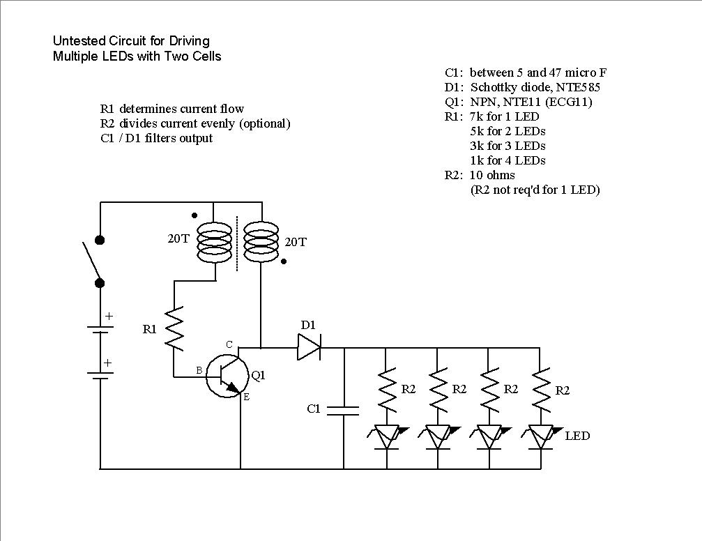
R1 is the throttle valve. As it gets larger, the LED
current gets smaller. The components can vary quite a bit.
Exact matches with the circuit diagram above are not necessary. The
Schottsky diode and capacitor can be deleted. They're used to smooth
out the output. Try using a 5k or 10k trim pot for R1 so output current
can be adjusted. Multiple LEDs can be put in parallel if their voltage
drops are about the same. Using a small resistor with each LED helps
even out current distribution.
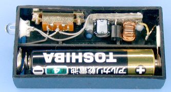
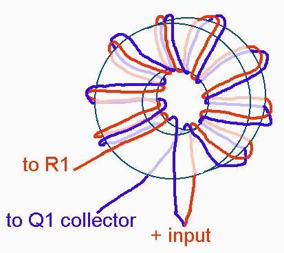
Coil winding detail
Modified One Transistor Design for Multiple LEDs
Regulated Version
back to main index